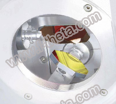
The f-theta laser scanners include the f-theta lens, galvanometer and the control system.
A scanner is a device that is able to move laser beam with two mirrors in two dimensions: first mirror moves along X axis and the second along Y axis. The mirrors are fixed on the galvanometers.
A galvanometer is a motor whose rotor can turn only for cca 20 degrees. Position of the galvanometer rotor is controlled by input voltage. Due to their lightness the rotor and the mirrors can move very fast. It leads to a fast marking (burning out) with the laser beam which is a great advantage comparing to mechanic appliances for cutting object out of different materials.
the control signals for the galvanometer scanners are transferred digitally from PC interface board to the scan head. The digital interface inside the scan head converts the data to analog values, that are subsequently transmitted to analog regulator circuits that control the position of the deflection mirrors.
Marking of an image is based on jump and mark commands.
Jump command is fast movement of the scanner mirrors while laser is switched off. As the result the laser focus jumps to a new position. If the laser system does not allowed fast switching, the jump speed must be set high enough to avoid any visible marking effect on the workpiece.
Mark command is movement of mirrors while laser is switched on. During it the laser focus moves along the specified line with a constant marking speed, producing a straight mark on the work piece.
Jump and mark commands are described with short vectors and because laser scanners are usually able to mark only straight lines, the conversion of the image into number of short lines is necessary.
This is just one of the problems that occur. Although some manufacturers of the components provide solutions, all problems can now be solved on PC in real time.
The X axis, Y axis and optional Z axis of the reference system for the image field must form a right-handed system. The origin of the reference system is the center of the image field.
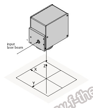
The size of the usable image field is determined by the maximum scan angle and the focal length of the objective or the distance between scan head and the image field.The scan head has a "typical image field". If the laser focus moves outside it, the scan head can be damaged due to excessive absorption of laser power.
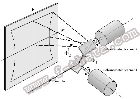
The deflection of a laser beam with a two-mirror system results in three effects:
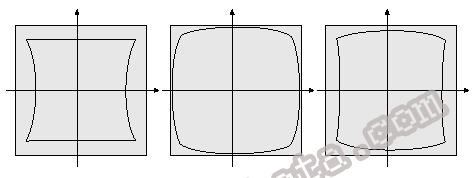
The arrangement of the mirrors leads to a certain distortion of the image field. The distortion arises from the fact that the distance between mirror 1 and the image field depends on the size of the scan angles of mirror 1 and mirror 2. A larger scan angle leads to a longer distance.The distance in the image field is not proportional to the scan angle.
If an ordinary lens is used for focusing the laser beam, the focus lies on a sphere. In a flat image field, a varying spot size results.By focusing the deflected laser beam with an F-Theta objective, two of three effects can be avoided:
- A direct proportionality between scan angle and distance in the image field is obtained.
- The focus lies on flat surface.
The F-Theta objective, however, causes a barrel-shaped distortion of the image field.
Source: SCANLAB's PC Interface Board RTC3 Manual. SCANLAB produces scan heads for the galvanometer scanners.